Q in coulombs, V in volts and C in farads. Therefore 1 F = 1 C·V⁻¹. Typical electronic values span roughly 1 pF to 1 mF.
Electronics Engineering · CHAPTER 02 · FOCUSED LESSON
Capacitors
Charge, electric fields, energy storage and time-dependent behaviour.
FROM ALI’S ORIGINAL ENGINEERING NOTESEXPLAINED, EXTENDED & VERIFIED
01 · ORIGIN & DEFINITION
Two conductors.
One electric field.
In October 1745, Ewald Georg von Kleist found that electrical charge could be stored using water in a glass jar connected to an electrostatic generator. His hand and the water acted as conductors while the glass separated them as a dielectric. The later Leyden jar made the same principle practical.
A capacitor—historically called a condenser—is a passive two-terminal component. It stores separated charge and energy in the electric field between two conductors divided by an insulating dielectric.
02 · CHARGE, VOLTAGE & CURRENT
Capacitance measures charge stored per volt.
Applying a potential difference moves +Q onto one plate and −Q onto the other. In steady-state DC, an ideal capacitor carries no continuous conduction current; current appears while its voltage is changing.
For a fixed capacitance, stored charge is proportional to applied voltage.
A faster voltage change requires more current. At constant ideal DC voltage, the rate of voltage change is zero.
The energy is electrostatic; an ideal capacitor stores it rather than dissipating it as heat.
03 · PHYSICAL CONSTRUCTION
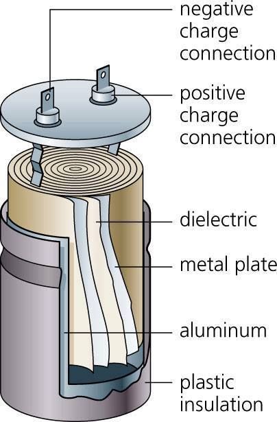
Geometry and dielectric set the capacitance.
The formula below is the ideal parallel-plate model. Real capacitors roll, stack or interleave long conductive films to create a large effective area in a compact volume.
INTERACTIVE PHYSICAL MODEL
309.9 pFParallel-plate structure
For two large parallel plates, the capacitance increases with plate area and permittivity, and decreases when the dielectric becomes thicker.
C=ε₀ εr Ad
C
Capacitance · farad (F)
ε₀
Vacuum permittivity · 8.854 × 10⁻¹² F·m⁻¹
εᵣ
Relative permittivity of the material · no unit
A
Overlapping plate area · square metre (m²)
d
Dielectric thickness · metre (m)
Calculated with SI values: A = 1.000e-2 m² and d = 1.00e-3 m.
04 · EQUIVALENT CAPACITANCE
Parallel adds area. Series adds separation.
The network rules are the opposite of resistor rules. Parallel capacitors share voltage and add capacitance; series capacitors carry equal charge and add reciprocal capacitance.
Same voltage · charges add
C1
C2
C3
Qeq = Q₁ + Q₂ + ··· + Qn
CeqV = C₁V + C₂V + ··· + CnV
Ceq = C₁ + C₂ + ··· + CnSame charge · voltages add
C1
C2
C3
V = V₁ + V₂ + ··· + Vn
QCeq=QC₁+QC₂+···+QCn
1Ceq=1C₁+1C₂+···+1Cn05 · RC TRANSIENTS
Charging is fast at first, then slows exponentially.
The resistor limits current while the capacitor voltage changes. The single number τ = RC sets the time scale for both charging and discharging.
INTERACTIVE RC LABORATORY
τ = 1.00 sCharge and discharge curves
Charge Discharge
Direction changes during discharge
Time t1.00 s
Charging VC7.59 V
Discharging VC4.41 V
|Current|0.441 mA
τ = RCVC,charge(t) = VS(1 − e−tRC)VC,discharge(t) = V₀e−tRCicharge(t) = VSRe−tRCidischarge(t) = −V₀Re−tRC
At 1τ: charging reaches 63.2% and discharging falls to 36.8%. At 5τ: the values are approximately 99.3% and 0.7%.
THE IDEA TO REMEMBERA capacitor does not simply “block DC.” It stores charge, opposes sudden voltage change and exchanges energy with the circuit according to its geometry, dielectric and time constant.