vL in volts, L in henries, i in amperes and t in seconds. With the passive sign convention, current enters the terminal marked positive.
Electronics Engineering · CHAPTER 02 · FOCUSED LESSON
Inductors
Magnetic fields, stored energy and opposition to changing current.
FROM ALI’S ORIGINAL ENGINEERING NOTESEXPLAINED, EXTENDED & VERIFIED
01 · ORIGIN & DEFINITION
Current creates a magnetic memory.
Michael Faraday’s work on electromagnetic induction established the principle behind the inductor. A practical inductor is usually a conducting wire wound into a coil, often around a magnetic core.
An inductor is a passive two-terminal component that stores energy in its magnetic field. It opposes a change in current—not current itself. Under the passive sign convention, its voltage is proportional to how quickly current changes.
02 · VOLTAGE, FLUX & ENERGY
An inductor resists rapid current change.
Current through an ideal inductor cannot jump instantaneously: an infinite change rate would require infinite voltage. Magnetic flux linkage provides the bridge between the electrical current and the magnetic field.
λ is flux linkage in weber-turns, N is the turn count and Φ is magnetic flux in webers. L = λ/i applies to a linear magnetic system.
Energy E is measured in joules. An ideal inductor stores energy in its magnetic field; winding resistance and core losses dissipate energy in a real component.
At the instant of switching, current is continuous. After a long time on ideal DC, di/dt = 0, so vL = 0 and the ideal inductor behaves as a short circuit.
03 · PHYSICAL CONSTRUCTION
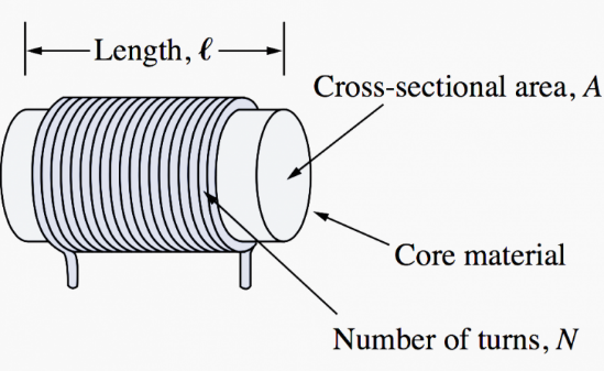
Turns, core and geometry set L.
The model below connects every formula parameter to the same labeled drawing. Change one physical property and see its exact effect on inductance.
INTERACTIVE PHYSICAL MODEL
341.1 µHIdeal solenoid
For a long, ideal and unsaturated solenoid, inductance grows with permeability, the square of the turn count and core area; it decreases as the magnetic path becomes longer.
L=μN²Aℓ
μ = μ₀μr · A = πr²
L
Inductance · henry (H)
μ
Core permeability · henry per metre (H·m⁻¹)
N
Number of turns · no unit
A
Core cross-sectional area · square metre (m²)
ℓ
Magnetic path / coil length · metre (m)
Educational ideal model: real ferromagnetic cores are nonlinear; μᵣ changes with frequency, temperature and magnetic flux density, and the core can saturate.
04 · EQUIVALENT INDUCTANCE
Series adds L. Parallel adds reciprocals.
These rules require uncoupled inductors: their magnetic fields must not create mutual inductance. When two coils are coupled, the mutual term M must also be included.
Kirchhoff’s voltage law
1 · VOLTAGES ADDvAB = v₁ + v₂ + ··· + vn
2 · USE v = L di/dtLeqdidt = L₁didt + ··· + Lndidt
3 · SAME di/dt IN EVERY COILLeq = L₁ + L₂ + ··· + Ln
Kirchhoff’s current law
1 · CURRENTS ADDdidt = di₁dt + ··· + dindt
2 · EACH BRANCH HAS di/dt = v/LvLeq = vL₁ + vL₂ + ··· + vLn
3 · CANCEL THE COMMON VOLTAGE1Leq = 1L₁ + 1L₂ + ··· + 1Ln
COUPLED-COIL EXCEPTIONTwo series coils: Leq = L₁ + L₂ ± 2M
Use +2M for series-aiding flux and −2M for series-opposing flux. The simple sum applies only when M ≈ 0.
INTERACTIVE NETWORK
Equivalent inductance laboratory
EQUIVALENT INDUCTANCE140.00 mH
WITH 12 V APPLIEDdi/dt = 85.7 A·s⁻¹
Series makes L larger, so the same voltage changes current more slowly.
05 · RL CHARGE & DISCHARGE
Inductors energize; their current does not jump.
In a DC series RL circuit, resistance limits the final current while inductance controls how quickly it is reached. During release, the inductor reverses its voltage polarity to preserve current continuity.
INTERACTIVE RL LABORATORY
τ = 2.5 msEnergizing and de-energizing
VS12 V
R100 Ω
L250 mH
Energize Release
Polarity reverses on release
Time t2.5 ms
Energizing iL75.9 mA
Release iL44.1 mA
Energizing vL4.41 V
Release vL-4.41 V
Stored energy0.719 mJ
τ = LRienergize(t) = VSR(1 − e−tτ)irelease(t) = I₀e−tτvL,energize(t) = VSe−tτvL,release(t) = −RI₀e−tτ
The release curve starts from I₀ = Vₛ/R, the steady-state current reached before the source is disconnected. At 1τ, energizing current reaches 63.2% of its final value while release current falls to 36.8%. At 5τ, the values are approximately 99.3% and 0.7%. The negative release voltage is the inductor reversing polarity to keep current flowing.
MEMORY RULEA capacitor preserves voltage.
A capacitor preserves voltage.
An inductor preserves current.
The capacitor stores energy in an electric field and resists sudden voltage changes. The inductor stores energy in a magnetic field and resists sudden current changes. That duality explains why RC and RL curves have the same exponential shape but exchange the roles of voltage and current.