Electronics Engineering · CHAPTER 00 · FOCUSED LESSON

Michael Faraday

A moving magnetic field induces current: the principle behind generators.

1831 · LondonALI'S NOTES · PAGE 8

Faraday discovered that change produces induction.

A magnet sitting inside a coil is not enough. Michael Faraday's galvanometer responded only while magnetic flux through the circuit was changing.

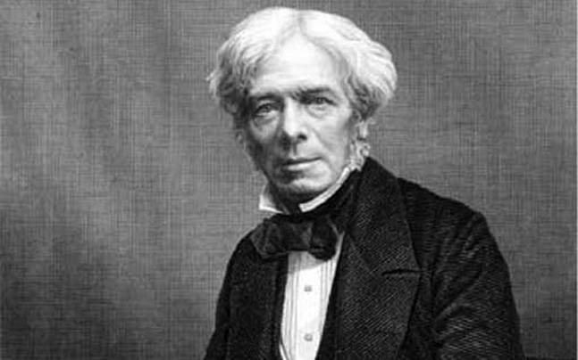
Portrait of Michael Faraday
Michael Faraday (1791–1867)Selected from Ali Chourba's original course document.
01
APPARATUS

A coil, a magnet and a galvanometer.

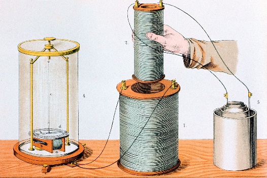
Faraday wrapped wire around a paper cylinder to make a coil and connected its ends to a galvanometer. The meter was sensitive to current direction: deflection to one side indicated one polarity, while deflection to the other side indicated the reverse.

He then moved a magnet back and forth inside the cylinder, deliberately changing the magnetic field passing through the coil's area.
02
OBSERVATIONS

Motion creates a pulse; stopping removes it.

As the magnet entered the coil, the needle deflected. When the magnet stopped—even while remaining inside the coil—the needle returned to zero. Pulling the magnet out produced a deflection in the opposite direction. Faster motion produced a larger rate of flux change and a stronger induced voltage.

The correct cause is not motion in isolation but changing magnetic flux linkage. The same effect can be produced by moving the coil, changing current in a nearby coil or changing the geometry of the magnetic circuit.

03
LAW AND LEGACY

Induced emf opposes the change that creates it.

Faraday's law relates induced electromotive force to the rate of change of magnetic flux. Lenz's law gives the direction: the induced response opposes the change that produced it. This is energy conservation expressed through circuit polarity.

Generators rotate conductors through magnetic fields; transformers vary current in one winding to induce voltage in another. Both are direct descendants of this experiment.

FORMULAE & SI UNITS

Every symbol, defined.

Read the equation together with the physical meaning and SI unit of each parameter.

Magnetic flux through one turn

For a uniform magnetic field over a flat coil area, this becomes Φ_B = B·A·cos(θ).

SymbolPhysical meaningSI unit
Φ_BMagnetic flux through one turnweber (Wb)
BMagnetic flux densitytesla (T)
dAInfinitesimal oriented surface areasquare metre (m²)
SSurface bounded by the wire turn
θAngle between B and the surface normalradian (rad) or degree (°)
Flux linkage of an N-turn coil

This form assumes every turn links the same magnetic flux.

SymbolPhysical meaningSI unit
λTotal magnetic flux linkageweber-turn (Wb·turn)
NNumber of turns in the coildimensionless (turns)
Φ_BMagnetic flux through one turnweber (Wb)
Faraday–Lenz law

The second equality assumes constant N and equal flux in every turn. The minus sign is Lenz's law: the induced voltage opposes the change that produces it.

SymbolPhysical meaningSI unit
Induced electromotive force (induced voltage)volt (V)
λMagnetic flux linkageWb·turn
tTimesecond (s)
NNumber of turnsdimensionless (turns)
Φ_BMagnetic flux through one turnweber (Wb)
THE IDEA TO REMEMBER

A steady magnetic condition produces no continuous induced voltage. The essential variable is the rate at which flux changes.

01

INPUT

Changing magnetic flux
02

DETECTOR

Galvanometer
03

DIRECTION

Opposes the change

COURSE SOURCE · “ELECTRONICS AND TECHNOLOGY” · ALI CHOURBA